 Coaching Centre
Transformers and power transmission
How a transformer works by mutual induction, the ideal transformer equations Vp/Vs = Np/Ns and VpIp = VsIs, why real transformers lose energy and how designers reduce the losses, and why the grid transmits power at hundreds of kilovolts.
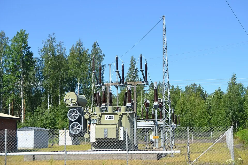
Electricity leaving the generators at Bayswater Power Station in the Hunter Valley is at roughly 20 kV. A few hundred metres later it is at 330 kV or 500 kV, racing towards Sydney on steel towers. By the time it reaches your power point it has been stepped down four or five times, to 230 V. Each step is done by a transformer: a machine with no moving parts that can be more than 99% efficient.
How a transformer works
A transformer is two coils of insulated wire wound on the same iron core, with no electrical connection between them. The primary coil is connected to an AC supply; the secondary coil is connected to the load.
- The alternating current in the primary produces an alternating magnetic field.
- The soft iron core channels almost all of this flux through the secondary coil.
- The flux through the secondary is continually changing, so by Faraday's law an alternating emf is induced in it, at the same frequency as the supply.
This is mutual induction (6E). A transformer only works with a changing current: on steady DC the flux is constant, so nothing is induced in the secondary (apart from a brief pulse at switch-on and switch-off), and the primary just heats up.
The ideal transformer
In an ideal transformer every turn of both coils links the same changing flux, ΔΦ/Δt. By Faraday's law the emf in each coil is proportional to its number of turns, so
$$\frac{V_p}{V_s} = \frac{N_p}{N_s}$$
- Step-up: more turns on the secondary (Ns > Np), so Vs > Vp.
- Step-down: fewer turns on the secondary, so Vs < Vp.
An ideal transformer also wastes no energy, so the power out equals the power in:
$$V_pI_p = V_sI_s$$
So if the voltage is stepped up by some factor, the current is stepped down by the same factor. A transformer doesn't create energy; it trades voltage for current. Note too that the load decides the current. With nothing connected to the secondary, $I_s = 0$, and an ideal transformer draws no power from the mains.
A transformer with 2000 turns on its primary is connected to the 230 V mains and supplies 12 V to a set of garden lights drawing 5.0 A. Assume it is ideal. Find the number of secondary turns and the primary current.
$N_s = N_p \times \dfrac{V_s}{V_p} = 2000 \times \dfrac{12}{230} = 104$ turns.
$I_p = \dfrac{V_sI_s}{V_p} = \dfrac{12 \times 5.0}{230} = 0.26$ A.
Power in = 230 × 0.26 = 60 W = power out, 12 × 5.0 = 60 W. The voltage went down by a factor of 19; the current went up by the same factor.
Real transformers: where the energy goes
Real transformers fall short of the ideal model in four main ways. Each one turns some of the input energy into heat.
| Limitation | What happens | How designers reduce it |
|---|---|---|
| Incomplete flux linkage | Some of the primary's field lines leak out of the core and never pass through the secondary, so Vs is lower than Ns/Np predicts. | A closed core of soft iron (high permeability) to channel the flux; winding the secondary directly on top of the primary; toroidal (ring-shaped) cores. |
| Resistive heating in the coils (copper losses) | The windings have resistance, so power $I^2R$ is lost as heat. It is worst in the high-current coil. | Thick, high-purity copper wire, especially for the low-voltage, high-current winding; cooling with oil or fans. |
| Eddy currents in the core | The changing flux induces currents in the iron core itself, which heat it. | Laminating the core: thin sheets of iron, each coated with insulating varnish, stacked so the insulation blocks the eddy current paths. High-frequency transformers use ferrite cores, which have very high resistivity. |
| Hysteresis | The core is magnetised one way then the other 100 times a second; this takes energy that becomes heat. | "Soft" magnetic materials such as silicon steel, which magnetise and demagnetise easily. |
Efficiency is the fraction of input power that comes out as useful output:
$$\text{efficiency} = \frac{P_{out}}{P_{in}} \times 100\% = \frac{V_sI_s}{V_pI_p} \times 100\%$$
Large power-station and substation transformers are typically 99–99.7% efficient. Even so, a 500 MVA transformer losing 0.5% is giving off about 2.5 MW of heat, which is why big transformers sit in tanks of circulating oil with radiator fins.
- Ideal core, 240 V in, 500 turns to 50 turns, 12 Ω load. Check Vs, Is and Ip with the two ideal equations.
- Increase the load resistance to 120 Ω. What happens to Ip? Explain why the primary current is set by the load.
- Change the secondary to 1000 turns and the load to 500 Ω. Is this step-up or step-down? Predict Vs, Is and Ip, then check them (480 V, 0.960 A and 1.92 A).
- Go back to 50 secondary turns and 12 Ω, and try each real core in turn, recording Vs and the efficiency. The air core wastes little energy but delivers only 6.0 V, because most of the primary's flux never passes through the secondary. Rank the three iron cores by efficiency (87.8%, 97.7%, 98.8%) and explain what each improvement fixes.
- Turn on DC supply. Explain the output.
Transmitting power: why high voltage?
Transmission lines have resistance, so a current I through a line of resistance R wastes power
$$P_{loss} = I^2R$$
For a given power P = VI, a higher transmission voltage means a smaller current. Step the voltage up by a factor of 10 and the current drops by 10, so the losses drop by a factor of 100. Thick lines would also reduce R, but the cost and weight of the conductors and towers would be enormous. Transformers make the high-voltage route cheap, and that is the main reason the world's grids run on AC.
A power station sends 50 MW along a line with a total resistance of 4.0 Ω. Compare the power lost at 33 kV and at 330 kV.
$I = \dfrac{P}{V} = \dfrac{50 \times 10^{6}}{33 \times 10^{3}} = 1.5 \times 10^{3}$ A; $P_{loss} = I^2R = (1515)^2(4.0) = 9.2$ MW, about 18%.
$I = 152$ A; $P_{loss} = (152)^2(4.0) = 0.092$ MW, about 0.18%.
Ten times the voltage, one-tenth the current, one-hundredth the loss. You explored this in Year 9 (6G); now you can see the transformer that makes it possible.
High voltage is dangerous and needs tall towers and long insulators, so it is only used where it pays: on long transmission lines. Near users the voltage is stepped down in stages, through 132 kV and 66 kV or 33 kV sub-transmission, then 11 kV distribution lines along streets, then a pole-top or pad-mounted transformer to 400 V three-phase and 230 V single-phase. Australia's nominal mains voltage has officially been 230 V since 2000 (it used to be 240 V, and many homes still measure close to 240 V). Inside appliances, more transformers step the voltage again: a microwave oven steps up to about 2000 V to drive its magnetron, while phone and laptop chargers step down, using small high-frequency transformers and a rectifier to produce DC.
Test yourself
An ideal transformer has 400 turns on the primary and 20 turns on the secondary. The primary is connected to 240 V AC. The secondary voltage is
Vs = 240 × 20/400 = 12 V.
In the transformer above, the secondary supplies 3.0 A. The primary current is
Ip = VsIs/Vp = 12 × 3.0/240 = 0.15 A.
Transformer cores are laminated mainly to reduce
The insulated sheets break up eddy current paths.
The voltage on a transmission line is doubled while the same power is sent. The power lost in the line
I halves, so I²R falls to one-quarter.
A transformer draws 500 W from the mains and delivers 475 W to its load. Its efficiency is
475 ÷ 500 × 100% = 95%.
Label the transformer.
Match each improvement to the loss it reduces.
A transformer only works with current, because the flux through the secondary must be changing. A transformer with more turns on the secondary than the primary is a step- transformer. In an ideal transformer the input equals the output. Transmission lines use high voltages so the is small, because the power lost is I²R. Thin insulated sheets in the core are called .
Evaluate the ideal transformer model as a description of a real transformer, referring to the strategies used to improve efficiency.
The ideal transformer model assumes that all the flux produced by the primary passes through every turn of the secondary, that the windings have no resistance and that the core wastes no energy. It predicts Vp/Vs = Np/Ns and VpIp = VsIs. Real transformers depart from it in several ways. Some flux leaks out of the core and never links the secondary, so the secondary voltage is lower than predicted; this is reduced by using a closed core of soft iron, winding the coils on top of one another, or using a toroidal core. The windings have resistance, so power I²R is lost as heat, especially in the high-current coil; thick, pure copper wire reduces this. The changing flux induces eddy currents in the core, heating it; laminating the core with thin insulated sheets, or using ferrite, confines these currents to small high-resistance paths. Repeated magnetisation of the core wastes energy as hysteresis, reduced by using soft magnetic alloys such as silicon steel. Large transformers are also oil-cooled to remove the heat that remains. With these strategies, large transformers reach efficiencies above 99%, so the ideal model is an excellent approximation for calculating voltages and currents. However, it cannot account for the heat produced or the small voltage drop under load, which matter for small or cheaply made transformers and for cooling design, so it is a useful but incomplete model.
Explain why electricity is transmitted over long distances at very high voltage, and why it is stepped down before it reaches homes.
The power transmitted is P = VI, so for the same power a higher voltage means a smaller current. The power wasted as heat in the lines is Ploss = I²R, so reducing the current greatly reduces the loss: increasing the voltage tenfold cuts the current to one-tenth and the loss to one-hundredth. Step-up transformers at the power station make this possible. However, very high voltages are dangerous and require tall towers, large clearances and heavy insulation, which is impractical near homes. Step-down transformers in substations and on poles therefore reduce the voltage in stages to 230 V, which can be used safely in homes with ordinary insulation.