 Coaching Centre
DC motors
The parts of a DC motor and what each does, the torque on a coil τ = nIAB sin θ, why a split-ring commutator is needed, and how back emf limits a motor's speed and current, with energy analysis and the classic make-your-own-motor investigation.
Put a cordless drill bit against a hard surface so it can't turn, and squeeze the trigger. The drill gets hot quickly and the battery drains fast. Let the bit spin freely and the same drill draws only a small current. A spinning motor is also a generator, and the emf it generates pushes back against the battery.
Parts of a DC motor
| Part | What it is | What it does |
|---|---|---|
| Stator (field magnets) | Permanent magnets or electromagnets fixed to the casing | Provide the external magnetic field the coil turns in |
| Armature and coil | Many turns of insulated wire wound on a soft iron core that can rotate | Carry the current; the motor effect on each side produces the torque. The iron core strengthens the field through the coil. |
| Axle | Shaft through the armature, on bearings | Transfers the rotation to the load |
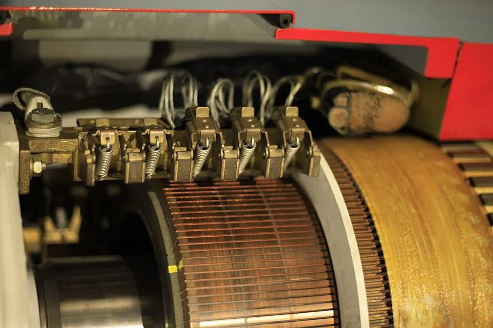
| Split-ring commutator | A copper ring cut into two halves, insulated from each other, fixed to the axle and connected to the ends of the coil | Reverses the current in the coil every half turn so the torque always acts in the same direction |
| Brushes | Graphite (carbon) blocks pressed against the commutator by springs | Make sliding electrical contact between the stationary supply and the rotating commutator |
Torque on a coil
Torque is the turning effect of a force: $\tau = r_{\perp}F = rF\sin\theta$, the force times its perpendicular distance from the axis. In a motor, consider a rectangular coil of n turns, with sides of length l perpendicular to the axle and width w, carrying current I in a field B. The two sides of length l carry current in opposite directions, so they feel equal and opposite forces $F = nIlB$, one up and one down. Together they make the coil turn.
Each force acts at a perpendicular distance $\tfrac{w}{2}\sin\theta$ from the axle, where θ is the angle between the field and the normal to the plane of the coil. So the total torque is $2 \times nIlB \times \tfrac{w}{2}\sin\theta = nI(lw)B\sin\theta$. Since lw is the area A of the coil:
$$\tau = nIA_{\perp}B = nIAB\sin\theta$$
- When the plane of the coil is parallel to the field (θ = 90°), the forces have their maximum lever arm and the torque is a maximum, nIAB.
- When the plane of the coil is perpendicular to the field (θ = 0°), the forces still act, but they pull straight outwards in line with the axle, so the torque is zero.
A rectangular coil of 100 turns measures 5.0 cm by 4.0 cm and carries 1.5 A in a 0.20 T field. Find the torque when (a) the plane of the coil is parallel to the field, and (b) the plane of the coil is at 30° to the field.
$A = 0.050 \times 0.040 = 2.0 \times 10^{-3}$ m2.
Plane parallel to B means the normal is perpendicular to B, θ = 90°: $\tau = nIAB = 100 \times 1.5 \times 2.0 \times 10^{-3} \times 0.20 = 0.060$ N m.
If the plane is at 30° to B, the normal is at 60° to B. $\tau = 0.060 \sin 60^\circ = 0.052$ N m. Always check which angle the question gives you.
Why the commutator is needed
Without a commutator, the coil would turn until its plane was perpendicular to the field, overshoot a little, and then the torque would pull it back. It would rock back and forth and settle in that position. The split ring solves this. Just as the coil passes the perpendicular position, the gaps in the ring pass the brushes and the connections swap over, reversing the current in the coil. The forces on each side reverse too, so the torque keeps acting in the same rotational direction.
A single coil still gives a lumpy torque that falls to zero twice a turn. Practical motors use many coils at different angles, each connected to its own pair of commutator segments, so that there is always a coil near its maximum. Curved pole pieces and an iron armature core make the field radial, so the plane of each coil stays parallel to the field across most of its rotation and the torque stays close to nIAB.
Back emf
A spinning motor coil is a coil rotating in a magnetic field, which is exactly what a generator is. As it turns, the flux through it changes, so by Faraday's law an emf is induced in it. By Lenz's law this induced emf opposes the change that causes it, which is the current driven by the supply. It is called the back emf. The current in the coil is set by the difference:
$$I = \frac{V_{supply} - \varepsilon_{back}}{R}$$
- At switch-on the coil isn't moving, so there is no back emf and the current is large, V/R. Big industrial motors use starter circuits to limit this inrush current.
- As it speeds up the back emf grows (it is proportional to the speed), so the current and torque fall.
- With no load the motor speeds up until the back emf is almost equal to the supply voltage. The tiny remaining current just overcomes friction. Back emf limits the top speed.
- Add a load and the motor slows, the back emf falls, the current rises and the torque increases until it matches the load. A motor automatically draws more current when it has more work to do.
- If the motor jams, the back emf drops to zero and the current is V/R all the time. With nothing turning, all the electrical energy becomes heat in the coil, which can burn out the insulation.
A 12 V DC motor has a coil resistance of 2.0 Ω. Running at its normal speed it draws 1.5 A. Find the starting current, the back emf when running, and how the input power is shared.
No back emf: $I = \dfrac{12}{2.0} = 6.0$ A.
$\varepsilon_{back} = V - IR = 12 - (1.5)(2.0) = 9.0$ V.
Input power $VI = 12 \times 1.5 = 18$ W. Heat in the coil $I^2R = (1.5)^2(2.0) = 4.5$ W. The rest, $\varepsilon_{back}I = 9.0 \times 1.5 = 13.5$ W, is converted to mechanical work. Efficiency (ignoring friction) = 13.5/18 = 75%.
If it jams, I = 6.0 A and all $12 \times 6.0 = 72$ W becomes heat, sixteen times as much heating as when running.
This is Lenz's law and conservation of energy working together. The back emf is what makes the motor take energy from the supply: the electrical power converted to mechanical power is exactly $\varepsilon_{back}I$. A motor with no back emf could do no work.
- Press Restart from rest at 12 V with no load. The starting current is 6.0 A (12 V ÷ 2.0 Ω). Watch the speed and current graphs and explain their shapes using back emf.
- When it reaches top speed, compare the back emf with the supply voltage. Why can't they ever be exactly equal?
- Increase the load torque in steps to 0.06 N m. Describe what happens to the speed and current each time.
- Turn on Jam the rotor. Read the current and the heating power. Why is a jammed motor dangerous?
- Turn off the commutator and restart. Describe what the coil does, and explain why using the torque equation.
- Halve the magnetic field. The top speed goes up. Explain why using the back emf. (This is how some motors are given a higher top speed.)
Test yourself
The torque on a DC motor coil is a maximum when
Then the normal is at 90° to B and the forces have their largest lever arm.
A 50-turn coil of area 3.0 × 10⁻³ m2 carries 2.0 A in a 0.40 T field, with its plane parallel to the field. The torque is
τ = nIAB = 50 × 2.0 × 3.0 × 10−3 × 0.40 = 0.12 N m.
The function of the split-ring commutator in a DC motor is to
Reversing the current keeps the torque in the same rotational direction.
A 24 V motor with coil resistance 4.0 Ω draws 2.0 A when running. The back emf is
εback = 24 − 2.0 × 4.0 = 16 V.
A load is added to a DC motor running at a steady speed. Which describes what happens?
Slower rotation means a smaller back emf, so more current flows and the torque increases to match the load.
Label the parts of the DC motor.
Which part does this job?
The turning effect on a motor coil is called . The current in the coil is reversed every half turn by the split-ring . As the coil spins it induces an emf that opposes the supply, called the emf. This emf is proportional to the of rotation. When a motor is first switched on, the current is at its . The direction of the back emf is given by law.
A DC motor is switched on and accelerates from rest to a steady speed, and then a load is applied. Analyse how the current in the motor's coil changes during this time. Refer to back emf and the law of conservation of energy.
At the instant the motor is switched on the coil is stationary, so the flux through it is not changing and no back emf is induced. The current is limited only by the coil's resistance, I = V/R, so it is at its maximum, producing a large torque that accelerates the coil. As the coil rotates in the magnetic field, the flux through it changes, so by Faraday's law an emf is induced in it. By Lenz's law this emf opposes the supply voltage that drives the rotation, so it is called the back emf. It is proportional to the speed, so as the motor speeds up the net voltage V − εback falls and the current I = (V − εback)/R decreases. The motor reaches a steady speed when the torque from this small current just balances friction. When a load is applied the motor slows down, the back emf decreases and the current increases, raising the torque until it matches the load at a new, lower steady speed. In energy terms, the electrical power supplied is VI. Part of this, I²R, is lost as heat in the coil, and the rest, εbackI, is converted into mechanical work. The back emf is therefore the means by which electrical energy is converted to kinetic energy, and Lenz's law must hold for energy to be conserved: if the induced emf aided the supply, the motor would accelerate without limit, creating energy.