 Coaching Centre
Generators and AC induction motors
How AC and DC generators produce an emf, the peak emf ε = NBAω, slip rings versus a split-ring commutator, why loading a generator makes it harder to turn, and how a three-phase AC induction motor works, including slip and synchronous speed.
Almost every joule of electrical energy you have ever used came from a coil of wire turning in a magnetic field. Coal, gas, hydro, wind and nuclear power stations all end in the same machine: a generator. And most of the motors turning fans, pumps and compressors around you have no brushes, no commutator and no electrical connection to their rotor at all.
The AC generator
A generator is a motor run backwards. Instead of supplying a current to make a coil turn, we turn the coil and an emf is induced in it. A coil of N turns and area A rotating at angular speed ω in a uniform field B has a flux through it of $\Phi = BA\cos\theta$, where θ = ωt is the angle between the field and the normal to the coil. The flux changes continuously, so by Faraday's law an emf is induced.
Using calculus (not required for the HSC, but it shows where the formula comes from), $\varepsilon = -N\dfrac{d\Phi}{dt} = NBA\omega\sin\omega t$. The emf varies sinusoidally, with a peak value
$$\varepsilon_{0} = NBA\omega = 2\pi NBAf$$
- The emf is zero when the plane of the coil is perpendicular to the field. Here the flux is a maximum, but for an instant it isn't changing, because the sides of the coil are moving parallel to the field lines.
- The emf is a maximum when the plane of the coil is parallel to the field. The flux is zero but changing fastest, because the sides are cutting straight across the field lines.
- The emf reverses every half turn, because the side that was moving up is now moving down. The output is alternating current with the same frequency as the rotation.
Slip rings connect the rotating coil to the external circuit. Each end of the coil is permanently joined to its own complete ring, and a brush rests on each ring. Because each brush always connects to the same end of the coil, the reversal of the emf in the coil appears in the external circuit as AC.
The peak emf can be increased by using more turns, a stronger field (electromagnets and an iron core), a larger coil, or by turning it faster. Turning it faster also increases the frequency, which is why power station generators are driven at a fixed speed: in Australia, 3000 rpm for a two-pole generator gives 50 Hz.
A generator coil of 200 turns has an area of 0.050 m2 and rotates at 50 revolutions per second in a field of 0.15 T. Find the peak emf, the rms emf and the frequency of the output.
$\omega = 2\pi f = 2\pi \times 50 = 314$ rad s−1.
$\varepsilon_0 = NBA\omega = 200 \times 0.15 \times 0.050 \times 314 = 471$ V, about 470 V.
For a sinusoidal output, $\varepsilon_{rms} = \dfrac{\varepsilon_0}{\sqrt{2}} = \dfrac{471}{1.414} = 333$ V. The rms value is the steady DC voltage that would deliver the same average power to a resistor.
One cycle of emf per revolution, so f = 50 Hz.
The DC generator
Replace the slip rings with a split-ring commutator and the generator gives DC. Just as the emf in the coil reverses, the commutator swaps the connections to the brushes. The output never changes direction: it is a series of half-sine "humps" that rise from zero to the peak and back, twice per revolution. It is DC in the sense that it flows one way, but it is not steady.
Practical DC generators smooth this ripple by using many coils at different angles, each with its own commutator segments, so the output stays close to the peak. Today, most DC is made by generating AC and converting it with diode rectifiers, because brushes and commutators spark and wear at high currents. A car alternator works this way.
| AC generator | DC generator | |
|---|---|---|
| Connection to coil | Two slip rings, one for each end of the coil | One split ring (commutator) |
| Output | Sinusoidal, reversing every half turn | One direction, pulsing from zero to peak twice per turn |
| Brush wear | Low (continuous contact) | Higher (sparking as gaps pass the brushes) |
| Used for | Power stations, wind turbines, alternators | Older dynamos, some small or specialised generators |
Generators and conservation of energy
With nothing connected, a generator coil spins freely; only friction opposes it. Connect a load and a current flows in the coil. Now the coil is a current-carrying conductor in a magnetic field, so it experiences the motor effect. By Lenz's law, the induced current flows in the direction that opposes the rotation that produces it, so the forces on the coil produce a torque against the rotation.
To keep the generator turning at the same speed, whatever drives it (steam turbine, wind, falling water) must supply a matching torque and do work. The more current drawn, the larger the opposing torque. This is conservation of energy: the electrical energy delivered to the load comes from the mechanical work done turning the coil. If the induced current aided the rotation instead, the generator would speed itself up while delivering energy, getting something for nothing.
The same thing happens in a power station. When demand rises across the grid, the generators slow slightly and the frequency drops below 50 Hz. Control systems respond by sending more steam or water to the turbines. The grid operator keeps the frequency very close to 50 Hz by matching generation to demand second by second.
A generator and a motor are the same device. A spinning motor generates a back emf, and a loaded generator experiences a back torque. Electric cars and trains use this in regenerative braking: when the driver brakes, the motor is switched to run as a generator, charging the battery, and the opposing torque slows the vehicle.
- With the default settings (60 turns, 0.40 T, 180 cm2, 20 rev/s), check the peak emf of 54.3 V using $\varepsilon_0 = NBA\omega$, then check the rms value of 38.4 V.
- Double the rotation rate to 40 rev/s. What happens to the peak emf and to the frequency of the output?
- Watch the coil and the graph together. Where is the coil when the emf is zero? Where is it when the emf is a maximum?
- Switch to the split ring and describe how the output graph changes.
- Connect the 10 Ω lamp at the default settings. The torque needed to turn the coil jumps from almost zero to a peak of about 1.95 N m. Explain why, using Lenz's law and conservation of energy.
The AC induction motor
The AC induction motor is the workhorse of industry: pumps, fans, compressors, conveyor belts, washing machines and many electric cars. It is cheap, tough and needs almost no maintenance, because its rotor has no electrical connection to the supply. No brushes, no commutator, no slip rings.
The stator and the rotating field
The stator has sets of coils around the outside, connected to a three-phase AC supply. The three currents peak one after the other, a third of a cycle apart, so the combined magnetic field they produce has a constant strength but a direction that rotates. With a 50 Hz supply and one pair of poles, the field turns 50 times a second, or 3000 rpm. With two pairs of poles (a four-pole motor), the field turns half as fast. The speed of the rotating field is the synchronous speed:
$$n_{sync} = \frac{120f}{p}$$
where n is in rpm, f is the supply frequency in hertz and p is the number of poles. A two-pole motor on 50 Hz has a synchronous speed of 3000 rpm; a four-pole motor, 1500 rpm.
The squirrel-cage rotor
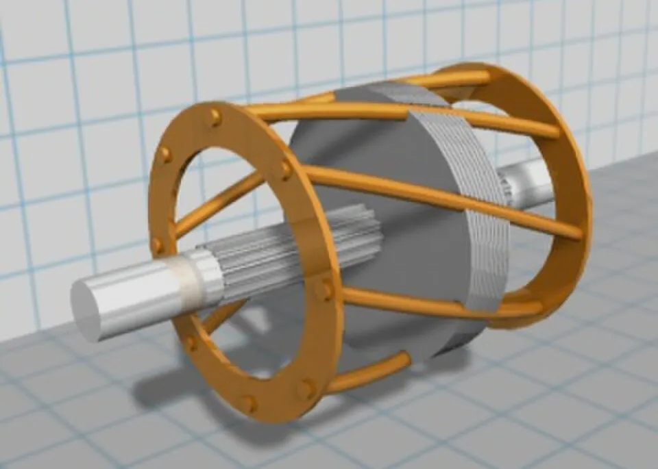
The rotor is a cylinder of laminated iron with conducting bars (aluminium or copper) running along it, joined at each end by a short-circuiting ring. Without the iron it looks like an exercise wheel for a pet, hence "squirrel cage". The iron concentrates the field through the rotor; the laminations reduce eddy currents in the iron itself.
How it turns
- The stator's field rotates past the bars of the stationary rotor, so the flux through each loop of the cage changes.
- By Faraday's law an emf is induced in the bars, and because the cage is a closed circuit with very low resistance, large currents flow.
- These currents are in a magnetic field, so they experience a force (the motor effect).
- By Lenz's law the forces act to reduce the relative motion between the field and the rotor, so they drag the rotor round in the same direction as the field.
This is the same physics as the magnet dragging a metal plate along in magnetic braking, turned into a motor.
Slip
The rotor can never quite catch up with the field. If it turned at the synchronous speed, there would be no relative motion between the bars and the field, no change in flux, no induced current and no torque. Friction would slow it down. So the rotor always turns a little slower than the field. The difference, as a fraction of the synchronous speed, is the slip:
$$s = \frac{n_{sync} - n_{rotor}}{n_{sync}}$$
A typical motor at full load has a slip of a few percent. When the load increases, the rotor slows, the slip increases, the field cuts the bars faster, and the induced current and torque increase to match the load. Like the DC motor and its back emf, the induction motor automatically draws more power when it has more work to do.
A four-pole induction motor runs on the 50 Hz mains. At full load its rotor turns at 1440 rpm. Find the synchronous speed and the slip.
$n_{sync} = \dfrac{120 \times 50}{4} = 1500$ rpm.
$s = \dfrac{1500 - 1440}{1500} = 0.040 = 4.0\%$.
- At the default 50% load (2 poles, 50 Hz), the field turns at 3000 rpm and the rotor at 2940 rpm, a slip of 2.0%. Increase the load to 100% and read the new rotor speed and slip.
- Push the load to 120%. The slip rises to 5.4% and the rotor current to 134% of its rated value. Why do motors overheat when overloaded?
- Switch to 4 poles. The field speed halves to 1500 rpm. Check this with $n = 120f/p$.
- Switch to 60 Hz (as used in the USA). What happens to the synchronous speed?
- Turn on Force the rotor to synchronous speed. The rotor current drops to zero. Explain why there is no torque.
Test yourself
A coil rotates in a uniform magnetic field. The induced emf is a maximum when
Then the flux is zero but changing at its greatest rate.
The speed of rotation of an AC generator is doubled. The peak emf and frequency of the output
ε0 = NBAω is proportional to ω, and the frequency of the output equals the rotation frequency.
A generator becomes harder to turn when a lamp is connected to it. This is best explained by
The current flows in the field, so the motor effect acts on it, and it opposes the motion that causes it.
A six-pole induction motor runs on a 50 Hz supply. Its rotor speed could be
nsync = 120 × 50 / 6 = 1000 rpm, and the rotor must turn a little slower than that.
The currents in the rotor of an AC induction motor are produced by
The rotor has no electrical connection; its currents are induced.
Label the parts of the AC generator.
Put the steps of the induction motor in order.
An AC generator connects to the external circuit through two rings. The peak emf is equal to NBA. In an induction motor the speed of the rotating field is called the speed. The rotor is often a cage. The rotor always turns more slowly than the field; the difference is called the . The energy delivered by a generator comes from the done turning its coil.
Explain how an AC induction motor works, and why the rotor cannot turn at the same speed as the stator's magnetic field.
The stator contains coils connected to a three-phase AC supply. Because the three currents peak at different times, the combined magnetic field has a constant strength but rotates at the synchronous speed, 120f/p. The rotor is a squirrel cage of conducting bars joined by end rings. As the rotating field sweeps past the bars, the magnetic flux through each loop of the cage changes, so by Faraday's law an emf is induced and, since the cage is a closed low-resistance circuit, currents flow in the bars. These currents are in the stator's magnetic field, so they experience forces (the motor effect). By Lenz's law the induced currents oppose the cause of the change, which is the relative motion between the field and the rotor, so the forces drag the rotor in the same direction as the field. If the rotor reached synchronous speed there would be no relative motion between the bars and the field, so the flux through the cage would stop changing, no emf or current would be induced and there would be no torque. Friction and the load would then slow the rotor. So the rotor always turns slightly slower than the field, and the difference (the slip) increases as the load increases.